Programmer’s Guide
Probe Detection
Overview

Probe detection involves a computer vision pipeline. Here is the general process:
1. Preprocessing (Diff): In this step, a difference image is created by comparing the current frame with the previous or background frame. This highlights the areas where motion is occurring between frames.
2. Line Detection: Hough line detection is used to detect straight lines in the difference image. This helps in identifying the angle and edges of the probe within the frame.
3. Tip and Base Detection: The algorithm then detects the pixel coordinates of the probe’s tip and base, determining the probe’s orientation, position, and bounding box within the frame.
4. Precise Tip Point: The precise tip point of the probe is calculated within the tracking boundary, improving accuracy. This ensures that the detected tip is as accurate as possible using the original image data.
5. Update Tracking Boundary: After detecting the probe tip, the tracking boundary is updated for the next frame. This allows the system to keep following the probe’s motion accurately in subsequent frames.
Please continue reading the rest of the document for detailed steps.
Preprocessing
Preprocess:
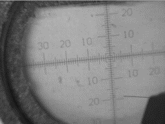
During preprocessing, the system prepares the current frame for probe detection by converting it to grayscale (if it’s a color image) and resizing it to a smaller size for faster processing. A Gaussian blur is applied to reduce noise in the frame, helping smooth out irrelevant details before comparison. The mask detection step follows, where the mask generator isolates the reticle from the background, ensuring the reticle region can be processed separately.
Code Reference:
parallax.mask_generator.MaskGenerator.process()
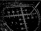
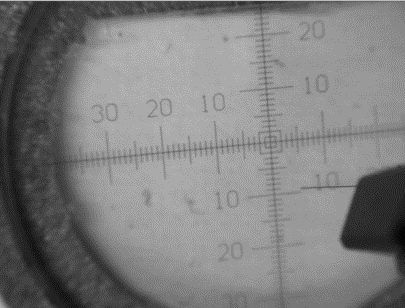
Create Reticle Zone:
 Original→
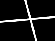 Reticle Zone→
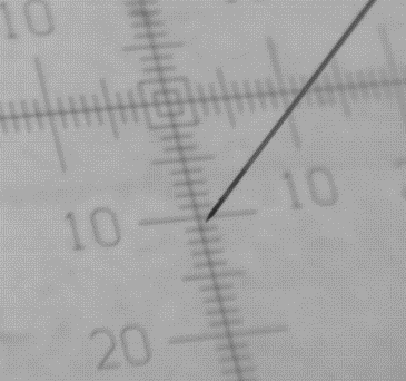 Use Case
If the reticle is detected for the first time and no reticle zone is set, a ReticleDetection object is created to get the reticle zone. This reticle zone helps localize the X and Y coordinates of the reticle and enhances probe detection by ignoring any detection when the probe tip is in the reticle region.
Code Reference:
parallax.reticle_detection.ReticleDetection.get_coords()
Create Mask:
 Original→
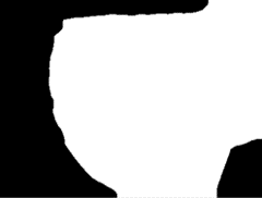 Mask
MaskThe mask is generated using
parallax.mask_generator.MaskGenerator.process(), which prepares the frame for the subsequent stages of probe detection.
Generate Diff Image:
The probe detection process comprises two main algorithms, with fallback logic that first tries the initial algorithm, which compares the ‘Curr’ vs ‘Prev’ frame, and if it fails, switches to the next algorithm, which compares the ‘Curr’ vs ‘BG’ frame.
Comparing ‘Curr’ vs ‘Prev’ Frame:
 Current Frame-Previous Frame=
 Diff→
Diff→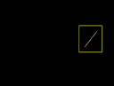 Processed
This algorithm compares the current frame (Curr) with the previous frame (Prev) to detect changes and identify the probe’s movement. The difference between the two frames is processed to highlight areas where motion occurs, enabling the system to track the probe’s movement.
Code Reference:
parallax.curr_prev_cmp_processor.CurrPrevCmpProcessor.update_cmp()Pros:
Better at handling noise, as differences are calculated between consecutive frames.
Works well when the probe moves relatively quickly.
Cons:
Ineffective for slow probe movement, as minimal changes between consecutive frames may be hard to detect.
Comparing ‘Curr’ vs ‘BG’ Frame:
 Current Frame-
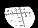 Background=
 Diff→
Diff→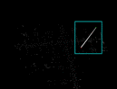 Processed
This algorithm compares the current frame (Curr) with a background frame (BG) that is captured when the probe is stationary or slow-moving. It detects the probe by highlighting the difference between the static background and the current frame, where the probe is in motion.
Code Reference:
parallax.curr_bg_cmp_processor.CurrBgCmpProcessor.update_cmp()Pros:
More effective at detecting slow-moving probes, as even slight motion is detectable.
Cons:
More sensitive to noise, as environmental changes or camera vibrations may be detected as motion.
Requires a reliable background frame, which may be challenging if there are frequent changes in the scene.
Note
The previous frame is updated when the probe is stopped, allowing the system to use the Comparing ‘Curr’ vs ‘Prev’ Frame algorithm, which is more robust to noise, during stopped motion. When the probe is moving, the system uses the Comparing ‘Curr’ vs ‘BG’ Frame algorithm more frequently, as it is more sensitive to detecting motion.
Line Detection
The parallax.probe_detector.ProbeDetector class is responsible for identifying the probe in an image using contour processing, Hough Line Transform, and gradient analysis.
Here is the general process:
Contour Preprocessing:
The first step involves detecting contours in the image. The contours help to isolate the probe from other irrelevant objects in the frame.
If the contour area is too small (below a threshold), it is considered noise and removed.s
This step is done using the
parallax.probe_detector.ProbeDetector._contour_preprocessing()method, which detects and cleans up contours based on specific thresholds.
Hough Line Detection:
Once the contours are processed, Hough Line Transform is applied to detect the line representing the probe.
In the first detection, the
parallax.probe_detector.ProbeDetector._hough_line_first_detection()method is used to perform the Hough Line Transform for the first time, identifying both the highest and lowest points of the probe. This is achieved by analyzing the gradients and finding the line that best represents the probe.In subsequent frames, the
parallax.probe_detector.ProbeDetector._hough_line_update()method is used to update the line detection. This method ensures that the updated lines still match the direction and angle of the probe detected in the previous frames.
Gradient Analysis:
During the Hough Line detection, the gradients of the detected lines are analyzed. The gradient gives information about the angle of the detected lines, which helps determine the orientation of the probe.
The
parallax.probe_detector.ProbeDetector._find_represent_gradient()method ensures that the detected lines have a representative gradient that corresponds to the angle of the probe.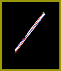 (Problem) Many gradients detected,
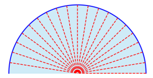 (Solution) Group gradients into Bins→
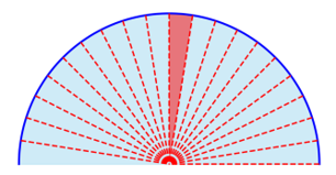 Representative gradient (Median value)
The probe’s direction (N, NE, E, SE, S, SW, W, NW) is calculated based on the relationship between the probe tip and probe base.
Code Reference:
parallax.probe_detector.ProbeDetector._get_probe_direction()method.
Tip and Base Detection
The parallax.probe_detector.ProbeDetector class is also responsible detect both the probe’s tip and base. These are updated during detection over time as new images are processed.
Here is the general process:
Tip and Base Detection:
Once the line detection is completed, the probe’s tip and base points are identified.
The
parallax.probe_detector.ProbeDetector._get_probe_point()method calculates these points based on the distance between the highest and lowest points detected during the Hough Line process.The tip is far from the mask image, which includes the probe holder, and the base is near the mask image. Based on this information, the system assigns highest and lowest points to tip and base.
 Original Image→
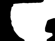 Mask→
Mask→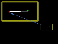 Assign Tip and Base (Tip is far from mask)
The probe tip and base coordinates are updated with each new frame, ensuring continuous tracking of the probe.
Refinement and Directional Check:
The probe’s angle is continuously refined over time. Each time a line is detected, its angle is compared with the previously detected angle. If the angles match, the probe’s direction is updated.
The probe’s direction helps to resolve the correct tip and base points in relation to the detected line, using methods like
parallax.probe_detector.ProbeDetector._get_probe_point_known_direction().
Distance Check:
To ensure accuracy, the system performs a distance check between the tip and base points to avoid false positives.
The
parallax.probe_detector.ProbeDetector._is_distance_in_thres()method ensures that the distance between the probe’s tip and base is greater than a certain threshold, helping to filter out noise or irrelevant objects.
Updating the Detection:
In the update detection step, the probe’s position is continuously updated by applying the Hough Line Transform again in each new frame. This ensures that the system can adapt to any changes in the probe’s position or angle over time.
Code Reference:
parallax.probe_detector.ProbeDetector.update_probe().
Precise Tip Point
The parallax.probe_fine_tip_detector.ProbeFineTipDetector class is responsible for accurately identifying the probe’s fine tip location.
Up to this point, detection has been performed on a resized, smaller image to reduce computation time. Now, the system switches to using the cropped original image to obtain the precise tip.
Preprocessing the Image:
The input image is first preprocessed by applying Gaussian blur to reduce noise, followed by a sharpening process using the Laplacian operator. The image is then binarized using Otsu’s thresholding method, preparing it for tip detection.
Code Reference:
parallax.probe_fine_tip_detector.ProbeFineTipDetector._preprocess_image().
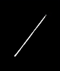
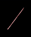
Validation Check:
Before proceeding, the system checks the boundary of the image to ensure there are no extraneous contours that could not represent the probe tip. This step ensures the image is valid for detecting the probe tip.
 Valid Tip
 Invalid Tip
 Invalid Tip
Code Reference:
parallax.probe_fine_tip_detector.ProbeFineTipDetector._is_valid().
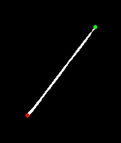
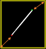
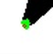
Detecting the Closest Centroid:
Using Harris corner detection, the system identifies potential corners (probe tip candidates, shown in green in the example image) in the preprocessed image. It then selects the closest centroid (corner, shown in red in the example image) to the initially detected tip and adjusts the tip position accordingly based on the probe’s direction.
Code Reference:
parallax.probe_fine_tip_detector.ProbeFineTipDetector._detect_closest_centroid().
Final Tip Coordinates:
After detecting and refining the tip, the system outputs the precise tip coordinates, which can be used for further processing, such as tracking or positioning tasks.
Code Reference:
parallax.probe_fine_tip_detector.ProbeFineTipDetector.get_precise_tip().
Update Tracking Boundary
In this step, the system updates the crop region, also known as the tracking boundary, which is used for detecting the probe in the next frame. Initially, the system attempts to detect the probe within the defined tracking boundary. If the probe is not detected, the system expands the search region to locate the probe.
The tracking boundary is updated under the following conditions:
Update Boundary:
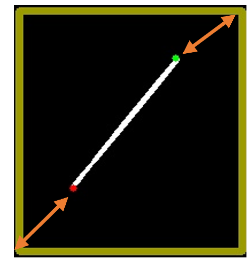
Base point + offset: The base of the probe is extended with an offset to allow for movement within the tracking boundary in the next frame.
Tip point + offset: Similarly, the tip of the probe is extended with an offset to account for its movement.
Update to Larger Search Region:
- The search region is expanded if:
Probe detection fails within the current crop region.
Either the tip or base of the probe is outside the existing boundary.
The crop_size is dynamically adjusted in a loop in
parallax.curr_prev_cmp_processor.CurrPrevCmpProcessor. If the detection fails or the probe points (tip or base) fall outside the crop region, the system increases the search region to continue detecting the probe in a larger area.If the probe is successfully detected and is within the updated boundary, the process continues. If the detection fails, the system increases the crop region by increments and tries again until a successful detection occurs or the maximum image size is reached.
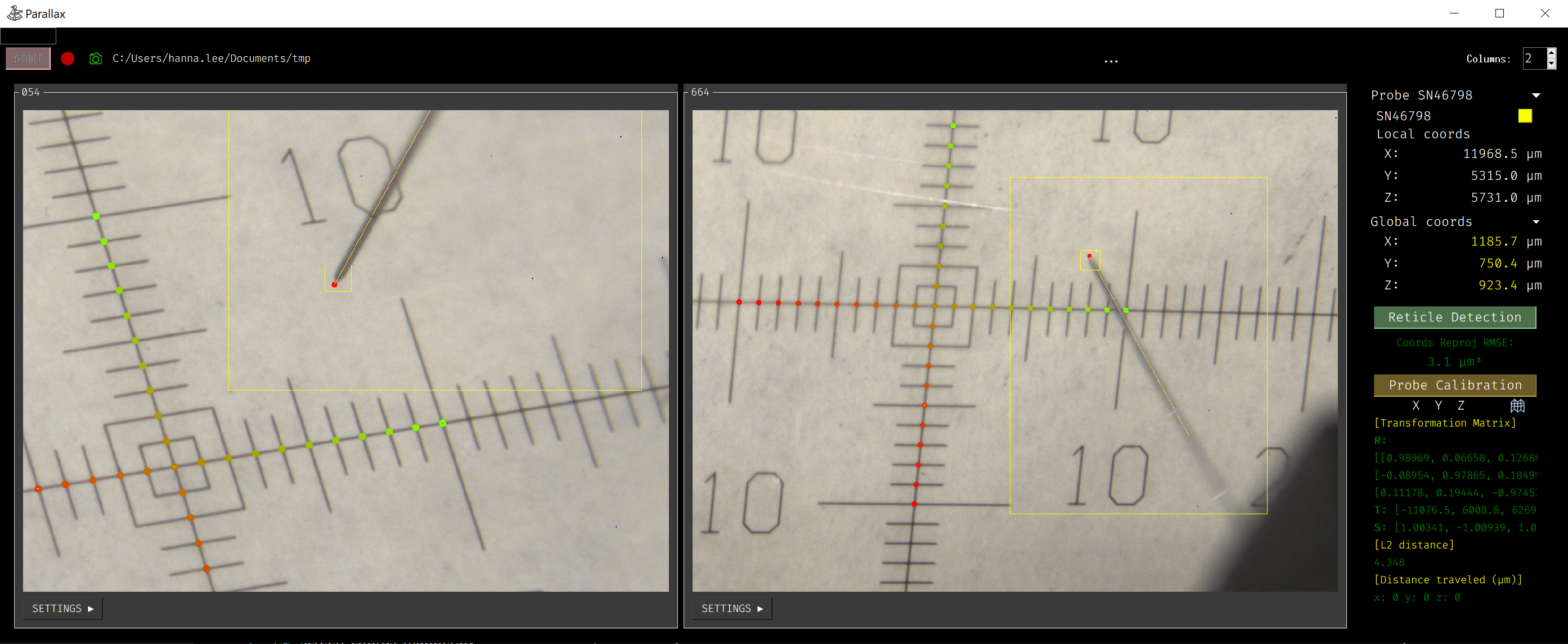
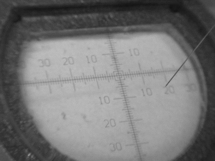
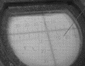
Debugging Mode
For debugging purposes, set the logger level to DEBUG in probe_detect_manager.py:
logger.setLevel(logging.DEBUG)This will allow you to use the
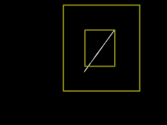
parallax.probe_detect_manager.ProbeDetectManager.Worker.debug_draw_boundary()method, which visualizes the tracking boundary and the probe’s tip location, and indicates which algorithm is used for detection.
Yellow: Comparison between the current frame and the previous frame.
Green: Comparison between the current frame and the background frame.
Here’s an example of how it visualizes the results: